Production
The board has been designed in Altium 14.3. The complete design-tree can be found in git.
Schematics
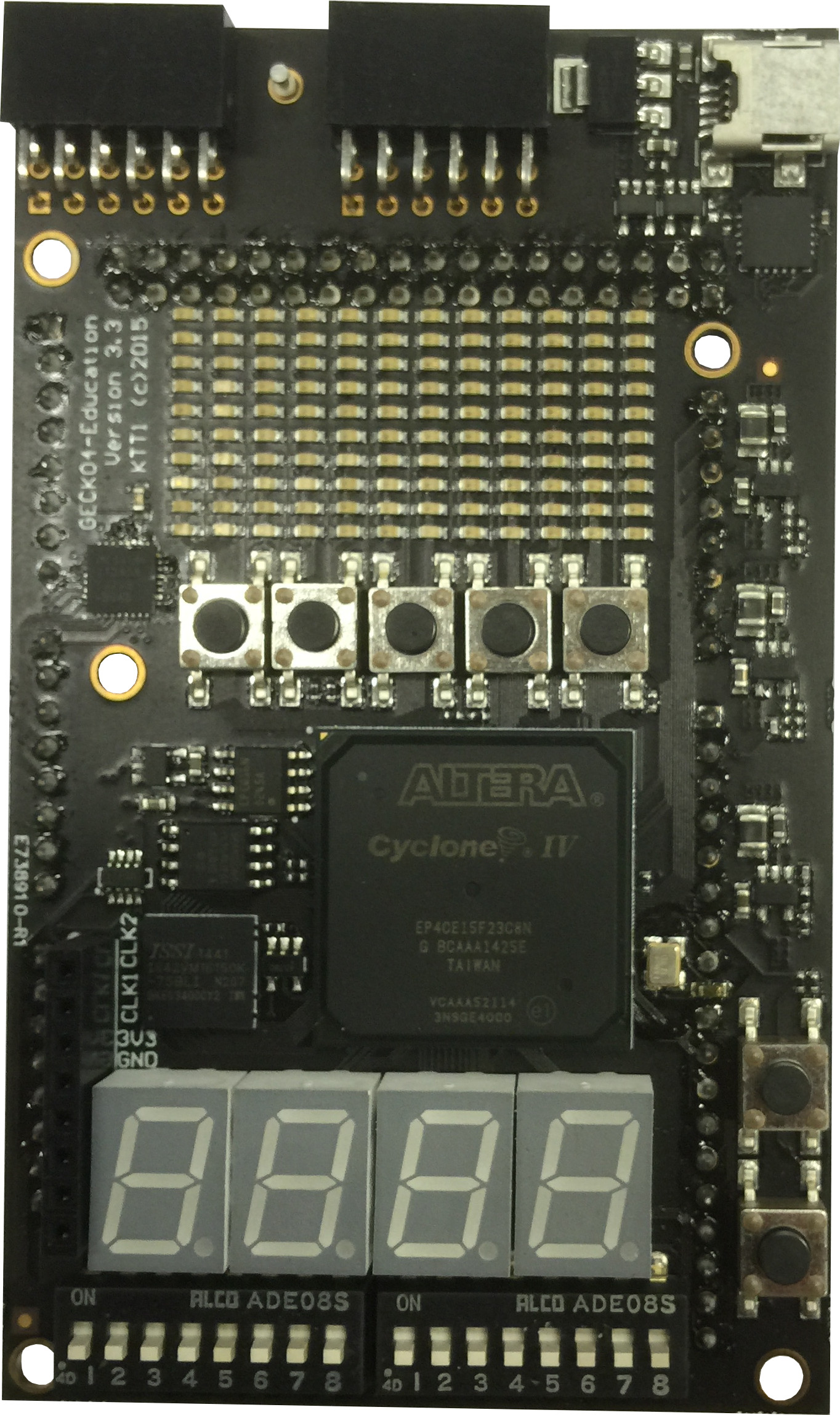
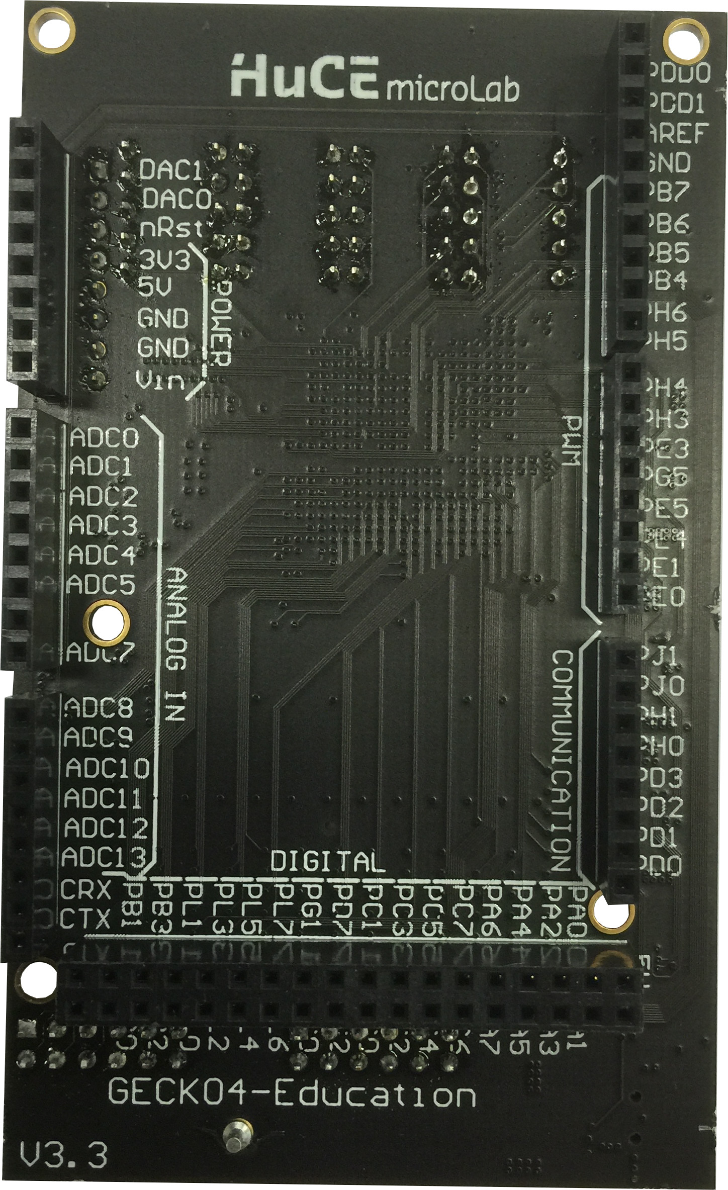
The schematics of the GECKO4-Education platform is provided .
PCB
The gerber files to produce the board can be found in this zip file. The PCB has been designed using the rules of the standard pool of Eurocircuits using 0.15mm via-hole-diameter.
Pick&place
Here you can download the Pick and place file to generate the board files for the Essemtec SMT Assembly System.
Components
We used Digikey as component supplier. All order reference numbers in the table below are order numbers of Digikey.
Designator |
Quantity |
Order number |
|---|---|---|
C2, C7, C10 |
3 |
490-6172-1-ND |
C1, C3, C4, C6, C8, C9, C11, C12, C13, C14, C15, C16 |
12 |
445-4112-1-ND |
C5 |
1 |
490-6287-1-ND |
D1, D2, D3, D4 |
4 |
TDSR1060-ND |
D1_1, D1_2, D1_3, D1_4, D1_5, D1_6, D1_7, D1_8, D1_9, D1_10, D1_11, D1_12, D2_1, D2_2, D2_3, D2_4, D2_5, D2_6, D2_7, D2_8, D2_9, D2_10, D2_11, D2_12, D3_1, D3_2, D3_3, D3_4, D3_5, D3_6, D3_7, D3_8, D3_9, D3_10, D3_11, D3_12, D4_1, D4_2, D4_3, D4_4, D4_5, D4_6, D4_7, D4_8, D4_9, D4_10, D4_11, D4_12, D5_1, D5_2, D5_3, D5_4, D5_5, D5_6, D5_7, D5_8, D5_9, D5_10, D5_11, D5_12, D6_1, D6_2, D6_3, D6_4, D6_5, D6_6, D6_7, D6_8, D6_9, D6_10, D6_11, D6_12, D7_1, D7_2, D7_3, D7_4, D7_5, D7_6, D7_7, D7_8, D7_9, D7_10, D7_11, D7_12, D8_1, D8_2, D8_3, D8_4, D8_5, D8_6, D8_7, D8_8, D8_9, D8_10, D8_11, D8_12, D9_1, D9_2, D9_3, D9_4, D9_5, D9_6, D9_7, D9_8, D9_9, D9_10, D9_11, D9_12, D10_1, D10_2, D10_3, D10_4, D10_5, D10_6, D10_7, D10_8, D10_9, D10_10, D10_11, D10_12 |
120 |
511-1303-1-ND |
J2, J3, J4, J6, J7, PMOD3 |
6 |
S7006-ND |
J8 |
1 |
S7008-ND |
J5 |
1 |
S7121-ND |
PMOD1, PMOD2 |
2 |
S5520-ND |
J1 |
1 |
H2959CT-ND |
L1, L2, L3 |
3 |
490-6700-1-ND |
R1, R2, R3, R4, R6, R7, R8, R9, R10, R11, R12, R13, R21 |
13 |
311-10.0KLRCT-ND |
R14, R15, R16, R17, R18 |
5 |
311-100KLRCT-ND |
R19 |
1 |
P680KLCT-ND |
R20 |
1 |
311-150KLRCT-ND |
S1, S2 |
2 |
1-1825058-9-ND |
SW1, SW2, SW3, SW4, SW5, SW6, SW7 |
7 |
450-1759-1-ND |
U1 |
1 |
544-2809-ND |
U3 |
1 |
544-2774-ND |
U12, U13 |
2 |
LTC4411ES5#TRMPBFCT-ND |
U11 |
1 |
LTC2632CTS8-LZ10#TRMPBFCT-ND |
U2 |
1 |
PIC18F14K50-I/MQ-ND |
U6, U8, U9 |
3 |
NCP1529ASNT1GOSCT-ND |
U7 |
1 |
TCR2EF25LM(CTCT-ND) |
U10 |
1 |
MAX11340ATJ+-ND |
U4 |
1 |
706-1313-ND |
U5 |
1 |
1274-1097-ND |
VR1 |
1 |
NCP1117ST50T3GOSCT-ND |
X1 |
1 |
631-1429-1-ND |
X2 |
1 |
1473-1237-1-ND |
Errata
Review / change orders for PCB version 3.3.1
Use footprint SOIC127P600X175-8N for U3
Create new larger footprint for U5 (208-mils body with)
MicroUSB J1 has to be placed closer to the PCB edge or needs milling. Actually it cannot be mounted flat on the PCB due to its mechanical dimensions. See 3D view of Altium design for details.
Wrong USB reference in Wiki BOM (mini USB type instead of micro USB type)
S25FL164K not recommended for new designs!