ADC/DAC
The GECKO4-Education platform contains an analog-to-digital converter (ADC) and a digital-to-analog converter (DAC) as shown in the figure below. Both the ADC and the DAC can be used with their internal reference voltage or they can use an external reference voltage provided at the AREF pin of the Arduino compatible connector.
Warning
The voltage on the AREF pin should always be greater than 0V and less than or equal to 3.3V!
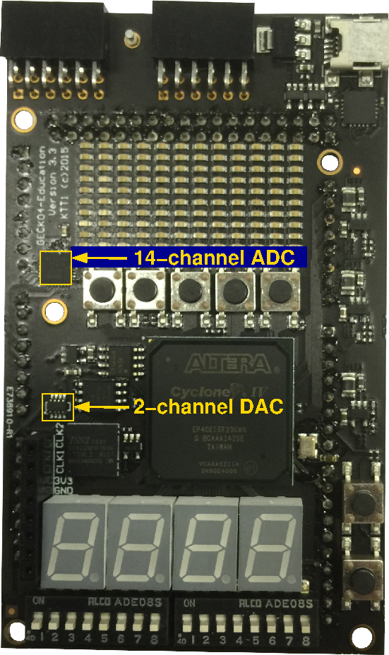
The ADC and DAC on the GECKO4-Education platform.
ADC
The analog-to-digital converter is a MAX11340 16-channel 10-bit ADC of which 14 channels are connected to the analog part of the Arduino compatible connector. The control pins of the ADC connected to the FPGA are listed in the table below.
Function |
Name |
FPGA pin |
|---|---|---|
Chip Select (active low) |
nCS |
PIN_J7 |
Serial clock |
SCLK |
PIN_H6 |
Serial data in |
Din |
PIN_J6 |
Serial data out |
Dout |
PIN_K8 |
Start conversation (active low) |
nCNVST |
PIN_H7 |
End of conversation (active low) |
nEOC |
PIN_K7 |
An example tcl-script for connecting the ADC pins to the FPGA is available here: adc.tcl.
DAC
The digital-to-analog converter is a LTC2632 dual channel 10-bit DAC. The two digital outputs (DAC0 and DAC1) are connected to the NC pins of the Arduino compatible connector. The control pins of the DAC connected to the FPGA are listed in the table below.
Function |
Name |
FPGA pin |
|---|---|---|
Chip Select (active low) |
nCS |
PIN_AB13 |
Serial clock |
SCLK |
PIN_AA13 |
Serial data in |
SDI |
PIN_V12 |
An example tcl-script for connecting the DAC pins to the FPGA is available here: dac.tcl.