Project details
| Name: | GECKObiomed | |
|---|---|---|
| Maintainer | hgb3@bfh.ch | |
| Revision: | 1.1 | |
| Development status: | stable | |
| Compatibility: | GECKO3 / GECKO4 | |
GECKO-biomed
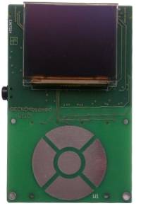
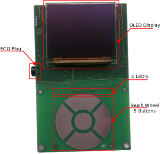
The GECKO-biomed AddOn is a signal processing education board which uses the micolink platform . With the GECKO-biomed a 3-wire ECG can be recorded and displayed. A capacitive touch wheel serves as user input device.
Hardware
Hardware Components
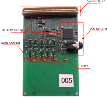
ECG Front-End
To record ECG signals the ADS1194 is used. The ADS1194 includes an analog front end as well as an 16-Bit ADC and needs a minimum of external components.
Features of ADS1194 (Datasheet):
- 4 Low-Noise Programmable Gain Amplifiers
- Programmable Gain: 1,2,3,4,6,8 or 12
- 4 16-Bit ADCs
- Data Rate: 125 SPS up to 8 kSPS
- CMRR: -105dB
- Built-In Right Leg Drive Amplifier, Lead-Off Detection, WCT, Test Signals
- SPI Data Interface

The development of the sensing circuit was done with the ADS1198 evaluation kit (Datasheet). The schematic which is provided in the datasheet was copied and only slightly adapted. The GECKO-biomed AddOn Board uses only 1 Channel of the ADS1194.
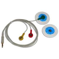
ECG-Cable
To record the ECG-Signal a 3 wire cable is used. The cable is connected to the GECKO-biomed by a 3.5mm audio jack.
Touch Buttons
As user input unit capacitive touch buttons are used. The buttons are made by copper layers on the PCB. The used sensing principle is called sigma-delta capacitive sensing.
Find detailed information in this paper: Delta Sigma
OLED Display
To display the ECG-signal a 160 x 128 OLED screen is used:

- Module Name: DD-160128FC-2A
- Driver IC: SEPS525
- Mode: OLED RGB
- Colors: 262 k
- Data Interface: 6800-/8080-Series MPU
- Control Interface: SPI
- Size: 1.69''
- Resolution: 160 x 128
- Used Voltage Booster: TPS61080
LED's
The GECKO-biomed has 4 LED's which are mounted on the backside of the PCB. The LED's can be used as optical feedback.
PCB Design
PCB design was done by altium designer ECAD. The design files are located in the following directory:
/mnt/data/fbe/microlab/projekte/intern/GECKO/GECKO_AddOn/GECKO_biomed/04_PCB/Version_1_1
For the next revision the power pins on the GPIO 1 have to be adapted to the new specification.
Schematic
System Bus
On GECKO-biomed only system bus 1 is used. For this reason GECKO-biomed can be used with GECKO3main and GECKO4main.
Powering
To power a GECKO stack by battery use the GECKO-robot or use a battery powered GECKO-simple!
| Component | 3.3 V | 3 V | 18 V |
|---|---|---|---|
| OLED Logic | ✔ | ||
| OLED Driver | ✔ | ||
| Touch Buttons | ✔ | ||
| ADS1194 Analog | ✔ | ||
| ADS1194 Interface | ✔ | ||
| LED's | ✔ |
For 3.3V the +3.3V line from the GECKO system bus 1 is used. 3V and 18V are generated out of VBAT.
PCB Layout
Final Result
Pinout
GECKO system bus 1 (IO-Bus 1)
GECKO3main: geckobiomed_gecko_3.ucf
GECKO4main: geckobiomed_gecko_4.ucf
| Pin | Name | GECKO3main FPGA | GECKO4main FPGA | Description |
|---|---|---|---|---|
| 1 | GND | - | - | System GND |
| 2 | GND | - | - | System GND |
| 4 | PHI2 | AF19 | AC25 | Switch Signal N-FET |
| 5 | GND | - | - | System GND |
| 6 | PHI1 | AE20 | AC26 | Switch Signal P-FET |
| 8 | GND | - | - | System GND |
| 11 | Q_Touch_1 | AD19 | Y25 | Button 1 discharge |
| 12 | GND | - | - | System GND |
| 13 | Q_Touch_2 | AE18 | Y26 | Button 2 discharge |
| 14 | D_Touch_1 | AD25 | W25 | Button 1 output |
| 15 | Q_Touch_3 | AE23 | W26 | Button 3 discharge |
| 16 | D_Touch_2 | AC21 | V25 | Button 2 output |
| 17 | Q_Touch_4 | AF22 | U26 | Button 4 discharge |
| 18 | D_Touch_3 | AC22 | U25 | Button 3 output |
| 19 | Q_Touch_5 | AE22 | T26 | Button 5 discharge |
| 20 | D_Touch_4 | AB20 | T25 | Button 4 output |
| 21 | LED4 | AB17 | R26 | LED 4 |
| 22 | D_Touch_5 | AB19 | R25 | Button 5 output |
| 23 | LED3 | AC19 | P26 | LED 3 |
| 25 | LED2 | AA25 | AB23 | LED 2 |
| 27 | LED1 | AB25 | U20 | LED 1 |
| 29 | GND | - | - | System GND |
| 30 | GND | - | - | System GND |
| 33 | GND | - | - | System GND |
| 34 | GND | - | - | System GND |
| 35 | VBAT | - | - | Battery Power |
| 36 | VBAT | - | - | Battery Power |
| 37 | VBAT | - | - | Battery Power |
| 38 | VBAT | - | - | Battery Power |
| 39 | VBAT | - | - | Battery Power |
| 40 | VBAT | - | - | Battery Power |
| 41 | GND | - | - | System GND |
| 42 | GND | - | - | System GND |
| 43 | GND | - | - | System GND |
| 45 | GND | - | - | System GND |
| 46 | GND | - | - | System GND |
| 47 | 3V3 | - | - | System 3.3 V supply |
| 48 | 3V3 | - | - | System 3.3 V supply |
| 49 | 3V3 | - | - | System 3.3 V supply |
| 50 | 3V3 | - | - | System 3.3 V supply |
| 51 | 3V3 | - | - | System 3.3 V supply |
| 52 | 3V3 | - | - | System 3.3 V supply |
| 53 | GND | - | - | System GND |
| 54 | GND | - | - | System GND |
| 56 | GND | - | - | System GND |
| 59 | GND | - | - | System GND |
| 60 | GND | - | - | System GND |
| 69 | OLED_BL_EN | W25 | J25 | OLED Backlight Enable |
| 70 | OLED_RESETB | W23 | H26 | OLED Reset |
| 71 | OLED_WRB | W22 | H25 | OLED Write or Read/Write select |
| 72 | OLED_RDB | V22 | D26 | OLED Read or Read/Write enable |
| 73 | OLED_CSB | W21 | D25 | OLED Chip Select |
| 74 | OLED_RS | U22 | N20 | OLED Data/Command select |
| 75 | OLED_D9 | V21 | N19 | OLED Image Data 9 |
| 76 | OLED_D10 | R20 | M20 | OLED Image Data 10 |
| 84 | OLED_D11 | U20 | U21 | OLED Image Data 11 |
| 85 | OLED_D12 | T20 | V23 | OLED Image Data 12 |
| 86 | OLED_D13 | R22 | U22 | OLED Image Data 13 |
| 87 | OLED_D14 | R21 | V24 | OLED Image Data 14 |
| 88 | OLED_D15 | P22 | T21 | OLED Image Data 15 |
| 89 | GND | - | - | System GND |
| 90 | GND | - | - | System GND |
| 91 | OLED_D16 | P21 | U23 | OLED Image Data 16 |
| 92 | OLED_D17 | N22 | T22 | OLED Image Data 17 |
| 93 | OLED_PS | N21 | U24 | OLED Select Interface Type |
| 94 | OLED_CPU | K22 | R21 | OLED Select CPU Type |
| 95 | OLED_ENABLE | L23 | T23 | OLED Video Enable |
| 96 | OLED_DOTCLK | T19 | R22 | OLED Dotclock |
| 97 | OLED_HSYNC | R19 | R24 | OLED Horizontal Sync Input |
| 98 | OLED_VSYNC | P20 | P21 | OLED Vertical Sync Input |
| 99 | OLED_VSYNCO | P19 | P23 | OLED Vertical Sync Output |
| 103 | ECG_SPI_DRDY | M19 | N24 | ECG Data Ready |
| 104 | ECG_RESET | L20 | N21 | ECG Chip Reset |
| 105 | ECG_SPI_START | L19 | N23 | ECG Start Conversion |
| 106 | ECG_PWDN | L25 | M22 | ECG Power Down |
| 115 | ECG_SPI_CLK | B10 | J24 | ECG SPI clock input |
| 116 | ECG_SPI_IN | B11 | K21 | ECG SPI data in |
| 117 | ECG_SPI_OUT | A10 | J23 | ECG SPI data out |
| 118 | ECG_SPI_CS | A11 | J22 | ECG SPI chip select |
| 119 | GND | - | - | System GND |
| 120 | GND | - | - | System GND |
Unlisted pins are unused
GECKO system bus 2 is unused.
Software
The GeckoBiomed has its own Matlab library. It can be started over the Menu (Applications→Microlab→Others→GeckoBiomed) in your desktop environment.