Table of Contents
Project details
| Name: | GECKO3power | |
|---|---|---|
| Maintainer | unknown | |
| Revision: | ||
| Development status: | stable | |
| Compatibility: | GECKO3 | |
GECKO3power
This is the electronic module of gecko3-robot.
It mainly consists of three parts:
- Power System to power GECKO3 modules
- Sensors
- Actuators and power drivers
Below you find the description of all sub modules of the board.
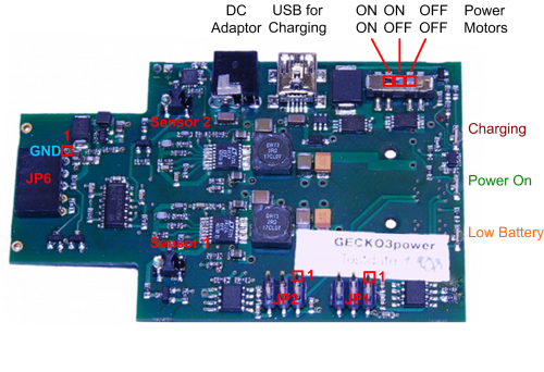
Schematic and Bill of Material
LEDs
- Red: Charging LED, lights during the charging process
- Green: Power LED, lights when the system is switched on
- Yellow: Battery empty LED, lights when you should recharge the Battery
Power Switch
Three position switch functions:
- off
- system on, motors off
- system and motors on
Motor driver
H-Brige Vishay Si9986
Full support H-Brige for forward, backward and brake.
Datasheet: Si9986
Application Note: Application Note
Controlling the motors
The two motors are controlled by the two signals INA and INB of each motor:
| Name | Description | FPGA output |
|---|---|---|
| M1_INA | Control signal A for motor 1 | AA21 |
| M1_INB | Control signal B for motor 1 | AB24 |
| M2_INA | Control signal A for motor 2 | AC26 |
| M2_INB | Control signal B for motor 2 | W24 |
The motor acts according to the control signal:
| Signal | Brake | +Dir | -Dir | Open |
|---|---|---|---|---|
| Mx_INA | 0 | 0 | 1 | 1 |
| Mx_INB | 0 | 1 | 0 | 1 |
Pinning of the Motor Connector JP1 and JP2
JP1 and JP2 connect the GECKO3power with the Maxon motors.
| Pin | Name | Description |
|---|---|---|
| 1 | MA+ | Motor positive output |
| 2 | +3V3 | Motor 3.3 V supply (independent from System 3.3 V) |
| 3 | Mx_ENA | Encoder output A |
| 4 | Mx_ENB | Encoder output B |
| 5 | GND | System GND |
| 6 | MA- | Motor negative output |
Motor and Decoder
Are documented under Motors.
Sensors
Line Sensor
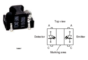
With these sensors and the on board circuit to realize a Delta-Sigma ADC (R-C element for integration, D Flip-Flop) you are able to measure the brightness of the floor. So you can build a robot that is following for example a white line on a darker floor.
Reflective Sensor Vishay TCND5000
- Peak operating range: 2 mm to 25 mm
- Daylight blocking filter
- High linearity
- Emitter wavelength 940 nm
Datasheet: tcnd5000
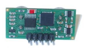
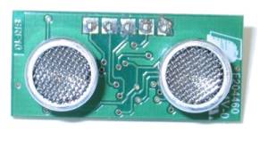
Ultrasonic Distance Sensor
Devantech SRF10
- Frequency 40KHz
- Max. Analogue Gain Variable 40 to 700 in 16 steps
- Units Range reported in uS, mm or inches
- Range from 30 to 6000 mm
- Connected to I2C Bus
- Size of only 32 x 15 x 10 mm
Datasheet with description of the I2C commands: srf10tech.htm
Battery
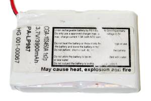
Contrell PA-LP987
- Cell Type Panasonic CGA103450
- Voltage 3.6 – 4.2 V
- Capacity 3900 mAh
- 1s2p type: 2 cells in parallel
Battery Charger LTC4075EDD
Charge through USB or with wall adapter.
To charge it using a USB cable you can use any USB connector on any other board connected to the system bus!
Wall adapter Input
The wall adapter input is a common barrel connector.
Connector
- Outer diameter 3.5 mm
- Hole diameter 1.35 mm
- Input current up to 4 A
- Input voltage 4.5 – 5.5 V
If you need a connector to plug into the robot you can use the one with order number 151300 at Distrelec
DC/DC Converter
The system voltage of GECKO3 modules is 3.3 V. The DC/DC Converter is the primary power supply for any 3.3 V component on other modules.
Supply
- Voltage: 3.3 V
- Available current: up to 3 A
60 to 120 pin adapter
This adapter connects the power module to the system bus electrically and matches the height and position of the system bus connector for the gecko3 robot.

Schematic and bill of material:
pcb_60pin_120pin.pdf
pcb_60pin_120pin_bom.pdf
Pinning of the 120 pin GECKO3 system bus.
