IP Core: GECKO3COM fifo
 This is the documentation about the GECKO3COM fifo IP core which is meant to be used in FPGA designs without an embedded processor. If you plan to build a microblaze based FPGA design use the GECKO3COM plb IP core.
Function
This core provides a simple FIFO and register interface to the USB data transfer capabilities of the GECKO3COM/GECKO3main system.
Usage

Main concept
As it is the main concept of USB this IP core is a client, this means that it never start operations by it self, it is always the host PC (USB master) who starts an transfer, independent of its direction.
As described in the GECKO3COM Introduction the USB Teast and Measurement Class (TMC) is used as the standard for communication. This IP core handles as much as possible from the USB TMC protocol and provides a simple and flexible interface to it. It is still needed to understand some concepts from the TMC protocol to implement and use this IP core correctly.
level of protocol handling, data in - data out. normally scpi messages but you are free to use it for every type of data you like.
This IP core handles most of the required things up to the level where you transmitt normally SCPI messages. This means that you get the data from your host PC as you send it to your TMC driver. Anything between is transparent to you.
Read the file GECKO3COM_simple_test.vhd to get an idea how to implement the procedures of receiving and sending data.
Things to consider
- All transfer size values represent number of bytes! The FIFO's are 32 bit wide, so with every FIFO read you get 4 bytes!
- Data sent by the host PC can arrive at any time. You have to handle it (at least 512 byte every 10s) to avoid that the host PC gets an timeout error.
- Never write data into the send FIFO before the host PC has send you a request for data.
- A message is the data that the application sends, a message can be transfered in one or more transfers.
- The host PC is able to abort a data transfer, independent of its direction. The client can not do such things. After an abort, the host PC assumes that all data is destroyed and will send a command that produces a response again before it will request any data.
Receiving data from the Host PC
The flag o_receive_newdata is set by the IP core when a correct TMC header is detected and data flows into the receive FIFO where it is available for your application. When this flag is set, the register o_receive_transfersize is valid and contains the transfer size value of this transfer.
When the transfer size is reached AND the flag o_receive_end_of_message is set, no more data will arrive from the host PC belonging to this message. If the transfer size is reached and the flag o_receive_end_of_message is NOT set the host PC will send more data in the next transfer, the message is not finished yet.
Sending data to the Host PC
As described in the main concepts the client, the IP core and where it is implemented, never sends data by its own. Always the host requests data and the IP core responds.
The flag o_send_data_request is set when a correct TMC header is detected and the host requests data. The register o_receive_transfersize contains the maximum number of bytes the client is allowed to send to the host.
To send the data write first your transfer size value (or the maximum allowed) to the i_send_transfersize register. Write it to the i_send_transfersize bus and activate the i_send_transfersize_en for at least one clock cycle. If you have more data to send than what you are allowed to (your transfer size value is bigger than o_receive_transfersize value) than you have to activate the i_send_have_more_data flag to signal this to the host. Keep it activated until you have send enough data to the host so that your transfer size value is smaller than the current o_receive_transfersize value.
Now data should be written to the send FIFO. The IP core generates the TMC response header and sends the data from the FIFO to the host until the given send transfer size value is reached.
The flag o_send_finished is set when all data is sent to the host and the IP core goes to its idle state.
Port description
| Generic name | Type | Default Value | Description |
|---|---|---|---|
| BUSWIDTH | integer | 32 | Vector size of the FIFO databuses |
| Port name | Direction | Type | Description |
|---|---|---|---|
| i_nReset | in | std_logic | Low-active, asynchronous reset |
| i_sysclk | in | std_logic | FPGA System Clock |
| i_receive_fifo_rd_en | in | std_logic | Receive FIFO read enable signal. o_receive_fifo_data will we valid one clock cycle after the read enable is activated |
| o_receive_fifo_empty | out | std_logic | Receive FIFO empty signal |
| o_receive_fifo_data | out | std_logic_vector(BUSWIDTH-1 downto 0) | Receive FIFO data |
| o_receive_transfersize | out | std_logic_vector(31 downto 0) | Transfer length read from the TMC header. The host will write this number of bytes to the device |
| o_receive_end_of_message | out | std_logic | All data expected to be received is available in the receive FIFO |
| o_receive_newdata | out | std_logic | A new valid OUT transfer header was detected. The o_receive_transfersize value is valid and new data will be available in the receive FIFO |
| i_send_fifo_wr_en | in | std_logic | Send FIFO write enable signal. The FIFO will store the data on the next rising edge of i_sysclk |
| o_send_fifo_full | out | std_logic | Send FIFO full signal |
| i_send_fifo_data | in | std_logic_vector(BUSWIDTH-1 downto 0) | Send FIFO data |
| i_send_transfersize | in | std_logic_vector(31 downto 0) | Number of bytes of the response data to be sent to the host. It must be lower or equal o_receive_transfersize |
| i_send_transfersize_en | in | std_logic | Send transfer size write enable signal. The i_send_transfersize value will be stored on the next rising edge of i_sysclk. This also signals to the IP core that data is ready to be sent to the host |
| i_send_have_more_data | in | std_logic | Set this signal if there is more data to be sent to the host than the maximum number of bytes requested by the host (Response data length greater than o_receive_transfersize) |
| o_send_data_request | out | std_logic | The host has requested data from the device. The o_receive_transfersize value is valid (This is the maximum allowed number of bytes to be sent). The core is waiting for data in the send FIFO and that a valid value is written to i_send_transfersize |
| o_send_finished | out | std_logic | Signals that the core is finished sending data to the host |
| o_rx | out | std_logic | Receiving data signalization |
| o_tx | out | std_logic | Transmitting data signalization |
| Interface signals to the EZ-USB FX2 | |||
| i_IFCLK | in | std_logic | GPIF CLK (GPIF is Master and provides the clock) |
| i_WRU | in | std_logic | Write request from GPIF |
| i_RDYU | in | std_logic | GPIF is ready |
| o_WRX | out | std_logic | Request to write to the GPIF |
| o_RDYX | out | std_logic | FPGA is ready |
| b_gpif_bus | inout | std_logic_vector(SIZE_DBUS_GPIF-1 downto 0) | Bidirectional data bus |
Constraints (ucf file snippet)
#  GECKO3main Module Revision 1.0
#-----------------------------------------------------------------------------

# connection clk and rst
net "i_nReset" loc = "AE19";

net "i_SYSCLK"		loc = "AF14";
net "i_SYSCLK" tnm_net = "SYSCLK";
timespec "TS_SYSCLK" = period "SYSCLK" 20.0 ns HIGH 50%; # 50 MHz system clock

net "i_IFCLK"  loc = "AA7";
net "i_IFCLK" CLOCK_DEDICATED_ROUTE = FALSE;
net "i_IFCLK" tnm_net = "IFCLK";
timespec "TS_IFCLK" = period "IFCLK" 20.83 ns HIGH 50%; # 48 MHz interface clock

# connection of controll bus signals
net "i_WRU"    loc = "AC5";
net "i_RDYU"   loc = "AB5";
net "o_WRX"    loc = "AC14";
net "o_RDYX"   loc = "AD14";

# connection of data bus signals
net "b_gpif_bus<0>"  loc = "AA12";
net "b_gpif_bus<1>"  loc = "AB12";
net "b_gpif_bus<2>"  loc = "AB13";
net "b_gpif_bus<3>"  loc = "AC13";
net "b_gpif_bus<4>"  loc = "AA14";
net "b_gpif_bus<5>"  loc = "Y14";
net "b_gpif_bus<6>"  loc = "W14";
net "b_gpif_bus<7>"  loc = "Y15";
net "b_gpif_bus<8>"  loc = "Y9";
net "b_gpif_bus<9>"  loc = "Y10";
net "b_gpif_bus<10>" loc = "Y11";
net "b_gpif_bus<11>" loc = "W11";
net "b_gpif_bus<12>" loc = "Y12";
net "b_gpif_bus<13>" loc = "W12";
net "b_gpif_bus<14>" loc = "Y13";
net "b_gpif_bus<15>" loc = "W13";
Logic utilization
This numbers show the logic utilization of the whole GECKO3COM_simple_test project which includes a bit more logic elements than the GECKO3COM fifo IP core alone.
| Resource Type | Used | Available (Spartan3 4000) | Utilization |
|---|---|---|---|
| Number of Slice Flip Flops | 909 | 55,296 | 1% |
| Number of occupied Slices | 804 | 27,648 | 2% |
| Total Number of 4 input LUTs | 1,137 | 55,296 | 2% |
| Number of bonded IOBs | 30 | 489 | 6% |
| Number of RAMB16s | 4 | 96 | 4% |
| Number of BUFGMUXs | 2 | 8 | 25% |
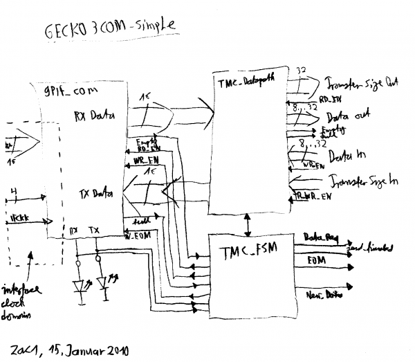
Internal structure